Start your beamtime
Here is a short introduction to start the experiment. Please open the following three interfaces to view, move, control and scan the required (pseudo) motors in order to execute your experiment during the beamtime.
Scanning, for XAS-measurements (or RIXSmaps): Scangui
RIXSmeasurements: Rixsclient
Solid state samples
Get to know the endstation chambers
As already mentioned in the previous section, the Veritas RIXS endsation has three chambers, for solid and gas samples, as labled in the figure:
Load Lock (LL) chamber
Upper chamber or transfer chamber. This chamber receives the sample plate(s) from LL chamber. This chamber also houses the sample rod (which is also the closed cycle He cryostat).
Q-chamber or the measurement chamber. It allows continuous motion of the scattering arm without breaking the vacuum.
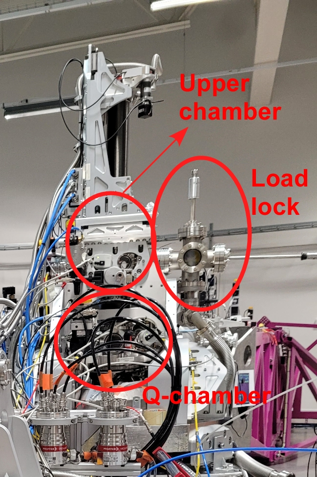
RIXS endstation chambers.
The solid samples can be in the form of powder (pelletized), single crystals or thin films. Here is a brief introduction of the steps you may follow to introduce your sample finally into the main chamber.
Here is a flowchart of the process that we usually follow.
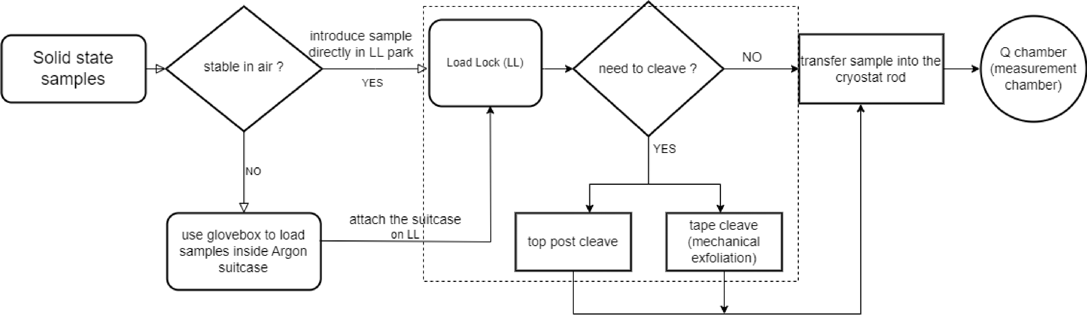
Solid state sample handling.
NOTE: If your sample is air sensitive, you can use the argon suitcase and mount it directly on the load lock. To avail this, you must use the glove box facility available in one of the chemistry labs.
Sample plate
We use Omicron flag-style sample plate and the sample is glued on it either using both-side copper tape (if you are not cleaving the sample) or some conductive epoxy (example: Epotek H21D conductive epoxy, or Epotek E4110 conductive epoxy). Currently we have stainless steel and copper sample plates, and if you need, we can ship a few plates to the your address. For this, the you must approach the beamline responsible atleast one month ahead of the scheduled beamtime.
The sample gluing on the sample plate must be done within one of the shaded regions depending on the choice of cryostat head during experiment. You may glue multiple samples in one sample plate (if the azimuth cryo-head is not used), however, it is recommended to follow the orientation as shown in the figure.
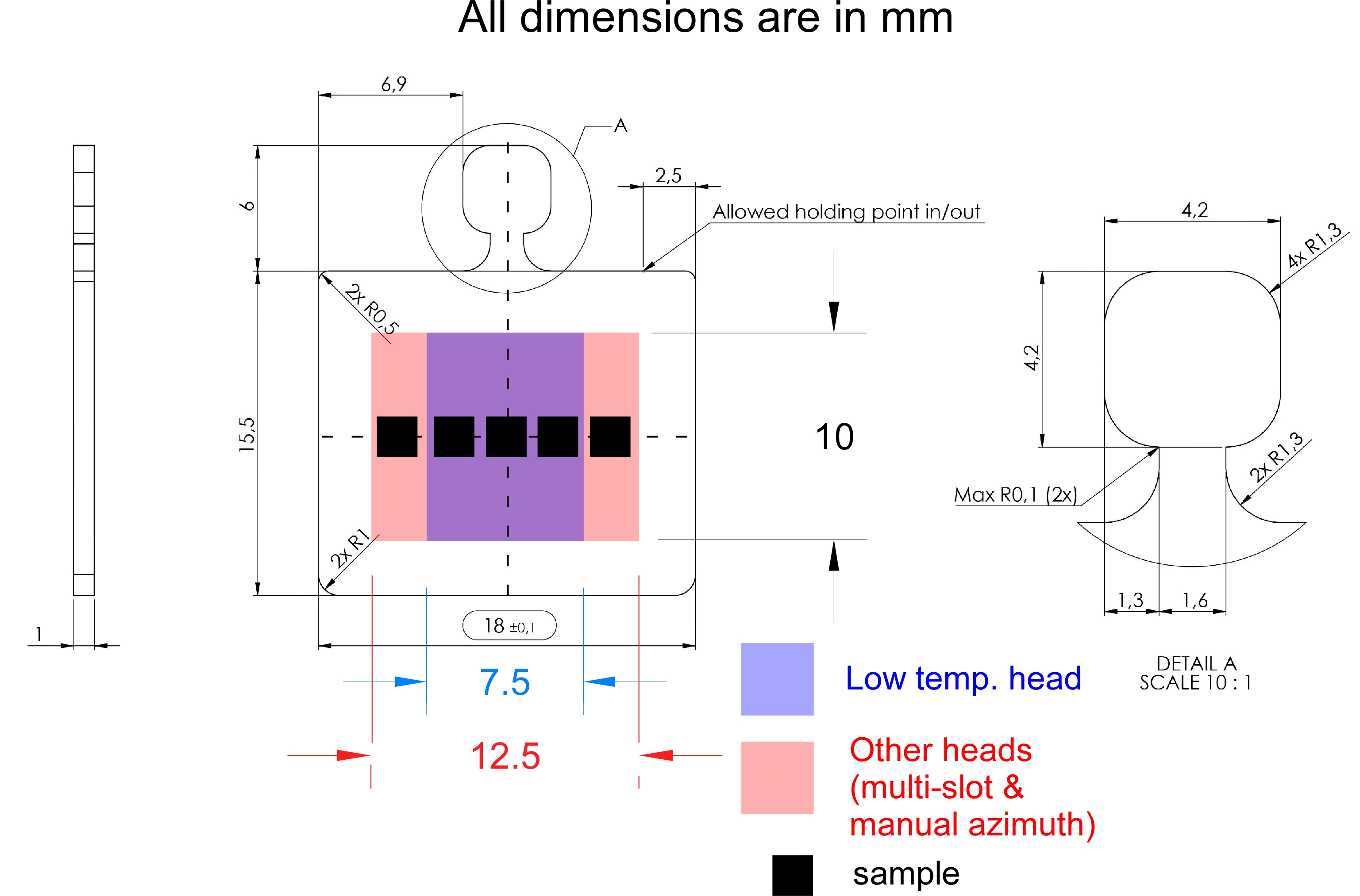
Sample plate and sample gluing regions.
Load Lock
The descrption about Load lock chamber moved to LoadLockChamber.
How to Cleave ?
The descrption about Load lock chamber moved to How2Cleave.
Transfer sample to the sample rod in upper chamber
Now its time to transfer the sample plate(s) to the sample rod in the upper chamber (UC). Prior to transfer, the manipulator must be set to sample transfer positions in order to receive the sample plate. Let us know how to do this :
You need the following softwares to align the sample rod’s sample holder surface parallel to the sample plate:
Open these softwares
Prior to sample transfer and subsequent experiments lets open and get familiar with the following two control panels / softwares:
Sample transfer positions
The sample transfer will differ depending on the samplerod and environment currently in use. Please not the differences when indicated Please continue working on the list below.
Using the QuickGUI, Move manipulator to the following positions depending on the choice of the sample rod head:
see ManupulatorForSolidStateSamples for position for transfer.
Transfer process: Follow the following steps to transfer the sample plate into the sample rod in the UC.
Close the valve between Q chamber and UC.
Check LL pressure is in the order of 10^-7 mbar.
Open the valve between the LL and UC.
Rotate the manipulator (a_mp1_yaw) to tight/loose position.
Tight/un-tight the screw holding the sample plate.
Remove if there is any sample in the sample rod and and park it in the LL sample garage.
Rotate the manipulator (a_mp1_yaw) to sample insert position.
Grab a new sample plate from LL garage.
Transfer it to the sample rod in the UC.
Rotate the manipulator (a_mp1_yaw) to tight/loose position.
Tight the screw.
Repeat the process between 5-11 if you have multiple samples.
Retract the transfer wobble stick and close the valve between LL and UC.
Open the valve between Q chamber and UC (safety feature: you cannot lower the manipulator if the valve is closed, yet its better to check and open the valve before lowering the manipulator).
Lower the manipulator to experimental position.
Now its time to find the samples. Go to “Finding samples” section.
Finding samples
Now its time to expose your sample to x-ray photons. Prior to this, check from synoptic if we have beam on the slit, and all the valves are open. If the sample rod is still in the UC, make sure to open the valve between Q-chamber and UC.
We first start with a 2D spatial map of the sample (a_mp1_x vs. a_mp1_y), after setting a_mp1_yaw at normal incidence. From this point on, you are going to use the control and acquisition software named ‘Scangui’. Here is how we do it:
see How2FindSample for detail.