Liqui Jet Chamber in general
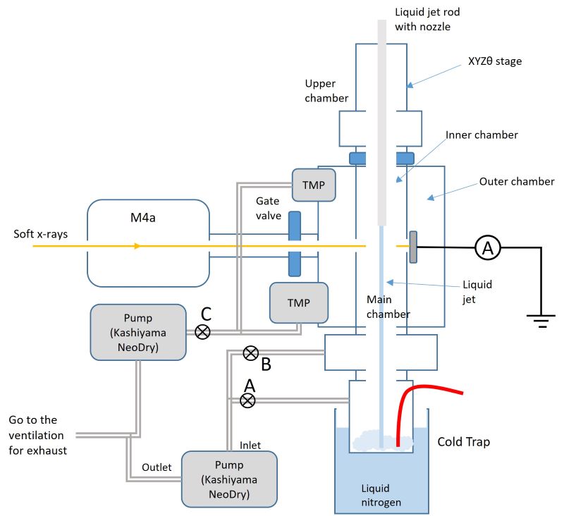
To accommodate liquid samples, the “Q-chamber” (used for solid and gas samples) is replaced with a differentially pumped chamber. This specific setup is required to handle the vacuum challenges posed by liquid jets while protecting the beamline optics. The chamber uses differential pumping to bridge the pressure difference between the liquid environment and the ultra-high vacuum (UHV) requirements of the Veritas beamline and spectrometer. Unlike the Q-chamber, which can rotate ±60°, the liquid jet chamber is not rotatable. Experiments are consequently limited to a fixed 90-degree scattering angle. The liquid jet chamber has an integrated cold trap and ice braker. The cold trap, which is cooled by liquid N2, is the chamber to store the liquid waste by freezing it. and the ice breaker is motorinzed rotatating rod which prevents ice buildup toward the jet stream. It is necessary to keep a cold trap while experiment to keep a vacuum by adding liquid nitrogen once every 1-2 hours. The cold trap has a capacity of around 2 liters as a volume, but it is recommended to remove the waste sample once per day.
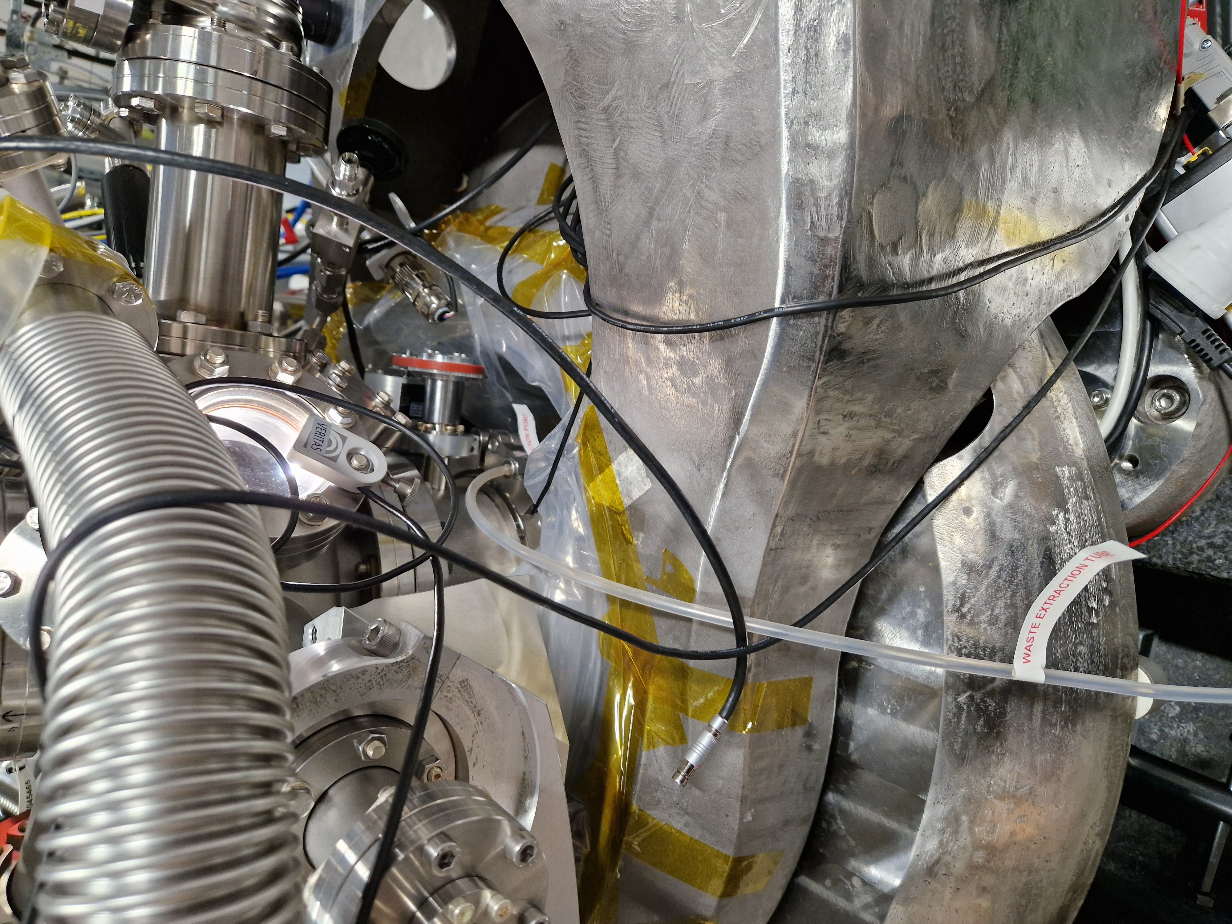
How it looks inside the chamber
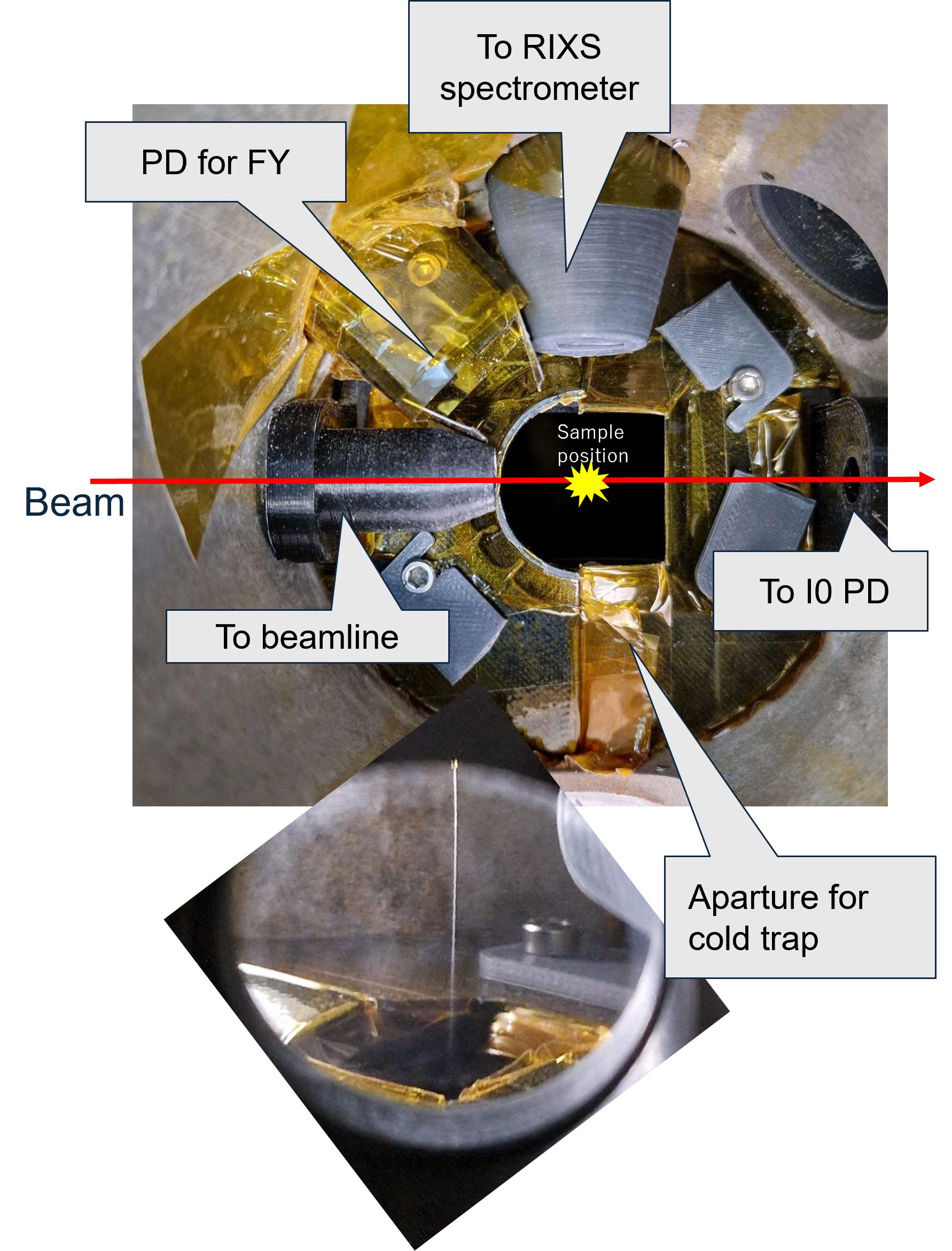
The follwing it picture from the top side of the inner chamber. There is a disk separating the cold trap and upper chamber to make a vacuum at uppchamber better. The liquid jet is passing through the hole of the separation disk and freezes in the cold trap. There is inernal differential pumping stage for the RIXS spectrometer side and beamline side by adding 3D printed parts.
There is a photo diode for fluorescence yield measurement (normmally Alminum coated photodiode, AXUV100TF400, is mounted as a detector). One glass window is also mounted as a viewport. The photo diode and glass window are easily exchanged by opning outer chamber access port.
 {width=600px}
Diagram of the differential pumping system
 {width=600px}
How to start the experiment
Since liquids are easily frozen in the vacuum, a liquid jet is necessary to start while the chamber is under air pressure. Therefore normal experiment procedure will start from the air pressure. The following are the steps to start expriment.
Start liquid jet
Start vacuum pumping
Find jet by mapping or a combination of Y scan and X scan
Start measurements
Each step will be explained in the following.
How to start a liquid jet
It is not possible to start a jet in a vacuum by freezing the jet while starting. Therefore, the following procedure needs to start from atmospheric pressure.
Move the jet nozzle near the separation disc between the cold trap and the upper chamber (typically 5-10mm lower than the beam poison. Please check with the camera to avoid a crash of the nozzle with the disc.)

Start liquid flow and wait for the pressure to increase well. Typically, pressure reaches 30-50 bar for water, depending on the capillary inner diameter. Increase the flow rate till the jet becomes straight enough. Normally, higher pressure (i.e., higher flow rate) makes the jet straight.
Start vacuum pumping (see procedure for pumping below)
Move the jet nozzle up and start tuning the position of the jet by monitoring the downstream PD.

How to start pumping
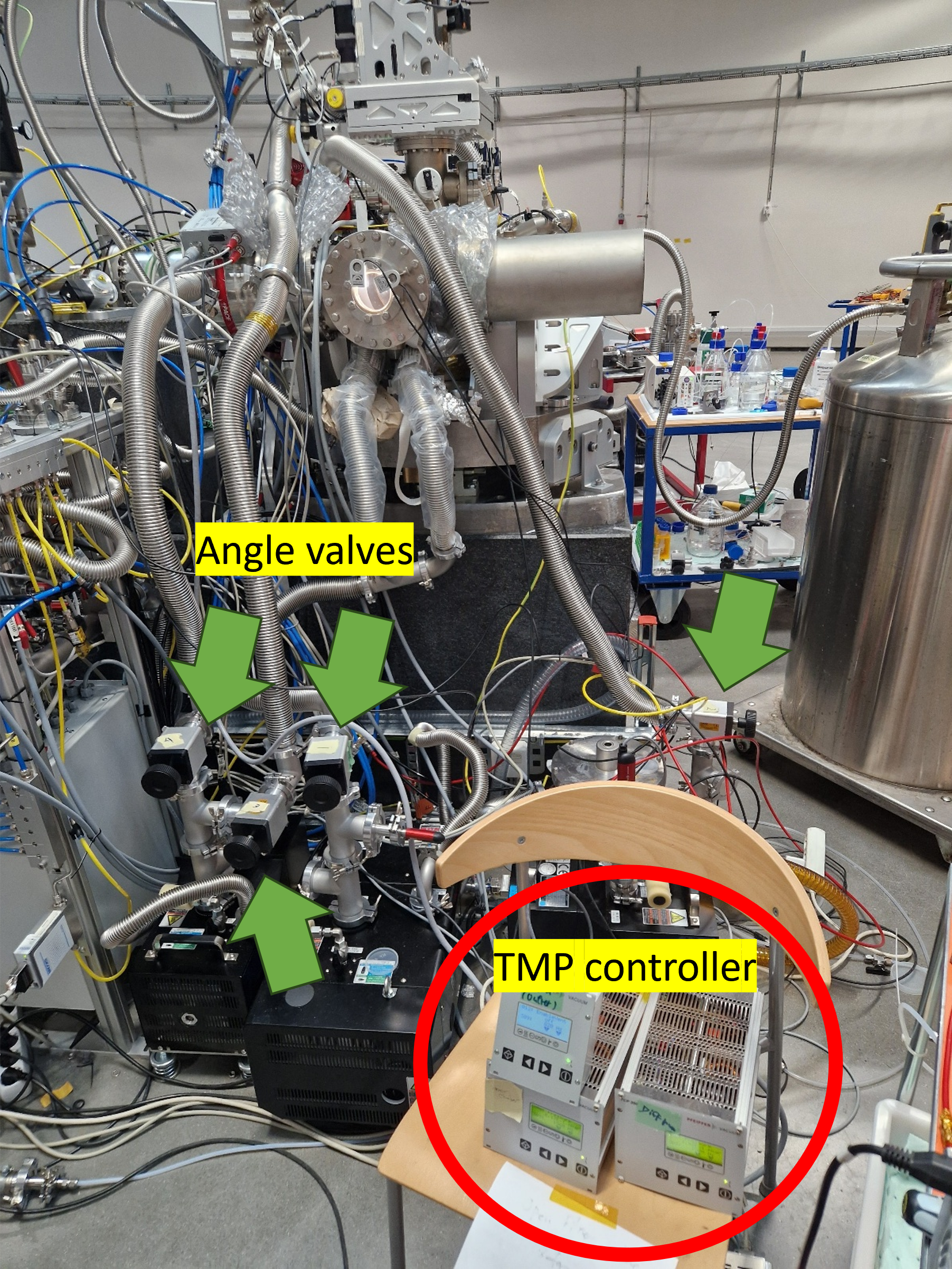
Open angle valves (1 and 2 after) for inner chamber pumping. Wait for the sound of vauum pump changes.
Open angle valves (3 and 4) for the inner differential pumping and the outer chamber pump.
Start three TMPs for the inner differential pumping and the outer chamber
Wait for the vacuum to recover.
Insert two filter valves (with !00nm Al filter) to protect the beamline and emission spectrometer.
 {width=300px}
How to stop pumping
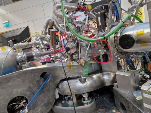
Confirm valves to the beamline and emission spectrometer are closed. It is recommended to close 2 gate valves from the endstation main chamber.
If filter valves were used, remove the filter( i.e., open the filter valve) just after closing the gate valves to prevent damage to the thin film windows.
 {width=300px}
Close angle valve(4 and 3) for outer chamer pumping.
Close angle valve(2 and 1) for innter chamber pump.
Stop two TMPs for outer chamber pumping
Wait for the chamber to be vented with air.
Procedure for Cleaning the cold trap
Note: The chamber is required to be at air pressure before starting.
Remove the nitrogen dewar at the bottom of the cold trap after removing the lift under the dewar. Since the gap under the chamber is narrow, you must tilt the drawer to do this. Please use cryogenic gloves for your safety.
Position the pot with water beneath the cold trap with the hot plate using the lift.
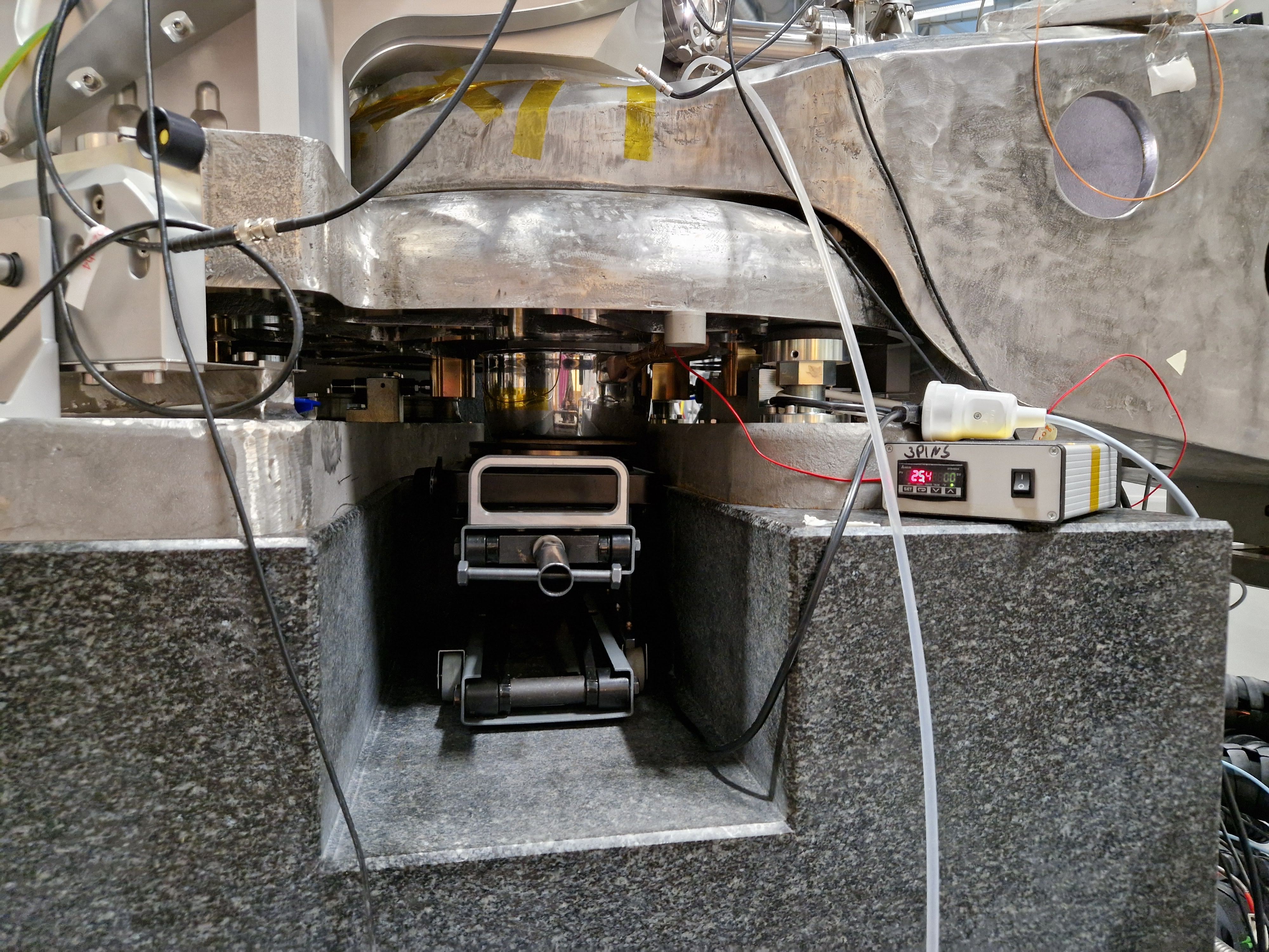 {width=300px}
If necessary, add liquid nitrogen to the solvent cold trap of the sample remover setup.
Locate the swagelock port (Labelled as chemical waste transfer port) with a blank plug attached to the cold trap. Connect the line from the sample remover setup to this port (tightening by hand is enough).
 {width=300px}
Connect the heater and thermocouples to the temperature controller, and activate the heating of the pot to around 50-85 degrees Celsius.
Start the small diaphragm pump of the sample remover setup to begin removing liquid from the cold trap.
Wait for the sample to melt and for it to flow into the glass canister. This whole process may take 20-60 minutes, including heating time, depending on the quantity of samples in the cold trap. If the glass canister becomes full, stop the liquid flow with the valve and the pump, replace the glass canister, and resume pumping.
Once all the samples have been removed from the cold trap, stop heating the pot, turn off the small pump of the sample remover setup, and carefully remove the pot and hot plate. Be cautious, as the hot plate will still be hot. Place a blank plug on the red line and seal it.
Detach the glass canister from the sample remover and securely close the cap. Temporarily store the chemical waste solutions in the canister, and dispose of them according to chemical safety regulations.
The system is now ready to start pumping the chamber.
Note: After cleaning the cold trap, the vacuum pressure in the chamber will initially be around 1 mbar due to solvent vapors when pumping starts. However, this pressure will improve once the cooling of the cold trap begins. The outer chamber should soon reach 1E-3 mbar and will gradually improve to around 5E-4 as cooling continues.